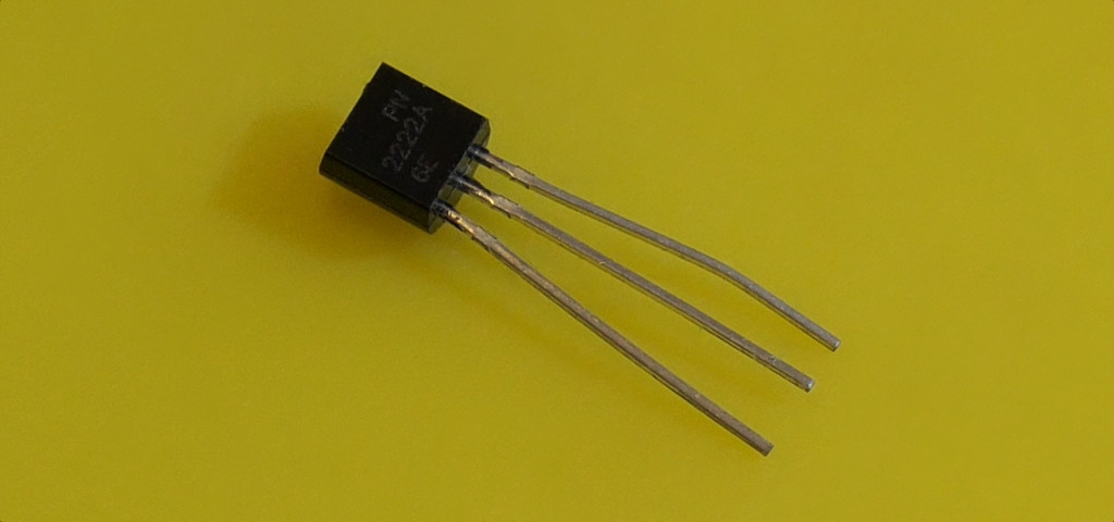
A controller pin can request an action without supplying the load’s current. A transistor is one way to make that separation. We will begin with an LED so the circuit stays easy to inspect, then identify the additional requirements for practical loads.
Identify the three leads
An NPN bipolar transistor has a base, collector, and emitter. Verify the exact manufacturer and package drawing. PN2222A, P2N2222A, and other similarly named parts can have different pin orders. The package’s flat face is not enough information.
| Connection | Destination or purpose |
|---|---|
| Transistor emitter | GND. |
| D3 | Through 2.2 kΩ to the base. |
| Base | Also connect through 10 kΩ to the emitter/GND. |
| 5 V | Through 1 kΩ to the LED anode. |
| LED cathode | Transistor collector. |
The pull-down holds the base near ground while the controller resets. When D3 is HIGH, a small current flows through the base resistor and the transistor conducts. The LED’s own resistor still limits its current.
Upload and inspect
Download the complete Arduino sketch
const byte basePin = 3;
void setup() {
  pinMode(basePin, OUTPUT);
  digitalWrite(basePin, LOW);
}
void loop() {
  digitalWrite(basePin, HIGH);
  delay(1000);
  digitalWrite(basePin, LOW);
  delay(1000);
}
The LED should alternate on and off each second. This circuit deliberately switches only a small load. The base current is approximately (5 − 0.7) / 2200 ≈ 2 mA, while the LED current is a few milliamps. The transistor’s voltage drops are approximate and depend on the device and current.
Move from demonstration to useful power switching
For a motor, solenoid, or relay coil, first determine the supply voltage, running current, startup/stall current, and required switching rate. Choose a transistor or driver for those conditions, with margin and appropriate heat handling. A small transistor is not automatically suitable because its headline maximum current exceeds the motor’s normal running current.
An inductive load needs a flyback path. For a simple low-side DC coil, a correctly rated diode goes across the coil with its cathode toward positive supply and anode toward the switched negative side. Driver modules may provide this already. The LED exercise itself is not inductive and does not need that diode.
A logic-level N-channel MOSFET is often more efficient for larger DC loads. Choose it by its specified on-resistance at your actual gate voltage; the threshold voltage only describes the beginning of conduction. Its gate also needs a defined off state. Mains switching is outside this breadboard exercise.
Troubleshooting and next steps
- Always off: recheck emitter/collector orientation and LED polarity.
- Dim or hot: unplug and inspect resistor values, current, and connections.
- Works until a real motor is attached: return to the load calculation, power supply, suppression, and driver choice.
Use a proper driver board for a stepper motor. Compare your transistor’s own datasheet with this example P2N2222A datasheet before wiring.