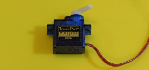
Some inexpensive servo motors can be easily converted to continuous rotation motors with just a few minutes of work. What this means is that the PWM signal will control the speed and direction of your freely rotating motor instead of setting its position within an 180-degree arc. In other words, it becomes a simple DC motor with a control circuit conveniently built in.
Inside the servo is a potentiometer that gives feedback to the internal circuit indicating the servo arm's current position. The circuit uses this information to maintain a stable position or to move to a new position.
For our continuous motor, we can either replace the potentiometer with a constant resistor or glue the potentiometer in place so it cannot change. The constant resistance at a particular value (typically around 2.2 kOhm) tricks the internal circuit into always reading that the servo arm is centered. When we send a PWM signal to change position, the internal circuit will start spinning the motor but will never see feedback that when the new position has been reached. It will just keep rotating until we send a PWM signal telling it to move to "center", a.k.a. the position corresponding to the constant resistance.
The gearing in the servo is also physically limited to 180-degrees of movement. For this conversion, we will need to remove the 180-degree limitation. Note: once modified, it will be very challenging to repair the servo to its original state. Consider this a permanent modification!
One way to find the true center point of the potentiometer is to connect the servo to an Arduino or other microcontroller and send the PWM signal corresponding to 90 degrees. Then simply glue it in place. Unfortunately, this method is imprecise and often needs to be fine-tuned in code to prevent the motor from slowly drifting when it should be stationary.
