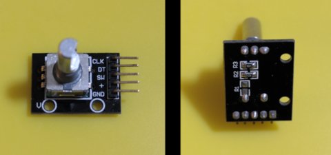
At first glance, some rotary encoders look a lot like the potentiometers used as knobs on radios and other control boards. They both can serve a similar purpose in providing rotational information to a circuit. However, these components are fundamentally very different:
- Rotary encoders will usually be able to spin through a full 360 degrees. Potentiometers almost always have a limited arc of rotation unless they've been either damaged or modified to spin freely (in which case they still only provide useful values over a portion of the circle).
- Potentiometers convey information by changing their resistance value. As the knob sweeps up and down, the resistance changes, which affects the analog voltage seen by other parts of the circuit. Rotary encoders emit digital pulses to indicate either incremental changes or, sometimes, the absolute position of the encoder. The value is then applied to digital logic elsewhere in the circuit.
The rotary encoder module in this example is an incremental encoder, allowing our microcontroller to detect when the knob is being rotated, and in which direction. If absolute position information is needed, the code will need to keep track of that information itself.
The module has five pins: GND, +VCC, SW, DT, and CLK.
- GND and +VCC are used to power the device. The voltage you apply to +VCC should match the logic level needed by the microcontroller that you will use to read the values—typically 3.3 or 5 volts. We will be using 5V to trigger a digital pin on the UNO.
- The SW pin (a.k.a. "switch") just indicates when the shaft of the encoder is pressed like a push button. It's not related to the rotary functionality.
- The DT and CLK pins provide the actual information about rotation. Your code (or library) will read voltage levels on these two pins to determine when the encoder is rotating and in which direction.
Debouncing
As the knob turns, it is possible to get several rapid voltage pulses during transitions, much like the "bouncing" that plagues other kinds of mechanical switches. Microcontrollers typically read their inputs so fast that, unless we do something about it, these bounces will be detected as multiple independent transitions when only one was intended.
One common way to "debounce" a switch is to use a capacitor and resistor to smooth out the transitions between low and high voltages. Another way is to write code to ignore transitions that happen faster than can be expected in normal situations. Hardware-based and software-based debouncing methods all have their own tradeoffs.
- Although RC filters are relatively cheap and simple, they are not free, and they do add something to the size and complexity of the circuit. If an existing microcontroller wasn't already being stretched to its limits, it is often more convenient to write some debouncing code instead of redesigning the circuit.
- Resistors and capacitors can change their characteristics over time, as the temperature changes, and so on. It's often not practical to change them once the circuit is being used somewhere. While it can also be challenging to update the code on the microcontroller, usually it is still easier than physically changing the circuit.
