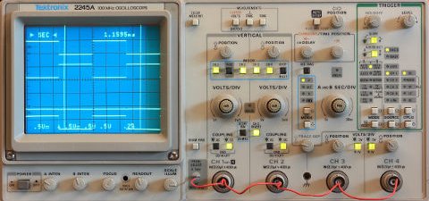
Here we will explore encoding data with analog signals or with digital signals that serve a purpose similar to analog signals.
Reading analog voltages
Each Arduino board has a row of pins capable of reading analog input. By "analog" we mean that the input data is determined by the voltage applied to the pin. Although in theory there are infinitely many levels between any two voltages, the actual number of distinct values is limited by noise and the type of hardware reading the voltages.
Arduino's analog pins connect to an analog to digital converter (ADC) that reads the voltage as a 10-bit value from 0 to 1023 (by default), which you can use in your code. The Arduino Due and Zero have a 12-bit ADC that extend the range to 0 to 4095, but only if you first adjust the resolution using analogReadResolution(12).
Reading from an analog pin is very easy using the analogRead(pin) function:
// Read the value from pin A1.
// Valid pins are A0 through A5.
int reading = analogRead(A1);
Another thing to consider with analog input is the reference voltage defining the maximum voltage in the range. This is 5v by default (or 3.3v on 3.3v devices). The reference voltage can be changed using analogReference(type) where type is one of: DEFAULT, INTERNAL, EXTERNAL, or (on Arduino Mega boards) INTERNAL1V1 or INTERNAL2V56.
Beyond binary: Writing PWM values
Recall the digitalWrite function, which toggles a pin between LOW and HIGH to indicate "off" and "on". This gives us only two distinct numerical values: 0 and 1.
The analogWrite function is able to represent up to 256 numerical values. However, analogWrite does not actually set an "analog" voltage as one might expect (i.e. some arbitrary voltage between 0v and 5v), but instead uses a technique called pulse width modulation, or PWM, to encode 0 to 255 using a digital signal.
In a nutshell, a PWM signal switches rapidly between LOW and HIGH voltages. The fraction of time spent in each HIGH pulse (called the duty cycle) is what represents the numerical value being sent. If a component is designed to work with PWM or if it reacts slowly to these rapid changes in voltage, such as with LEDs, the end result is similar to supplying a real analog voltage.
For some components, you will have to introduce your own circuitry to smooth out the pulses and produce a true analog voltage. This can be accomplished with a small low-pass filter circuit involving a resistor and a capacitor. This is called a digital-to-analog converter, or DAC.
We will rely on the relationship
fcarrier = 1 / 2πRC.
Here, fcarrier is the frequency of the PWM square wave, R is the resistance, and C is the capacitance. You should check the specs for your particular Arduino board, but the frequency is probably 488 Hz or 976 Hz when using analogWrite. It is also possible to encode the signal manually at other frequencies.
To use PWM, you need to use one of the designated pins on the Arduino device, typically 3, 5, 6, 9, 10, or 11. Look for a small, wavy line next to the pin.
Arduino has a built-in function called analogWrite for producing PWM signals.
analogWrite accepts an 8-bit number which represents the duty cycle of the PWM signal in a range from 0 to 255.
Note: On devices with DAC pins, using analogWrite on those pins will (or at least should) produce a true analog voltage instead of PWM.
// For a device connected to pin 3
const byte PIN_NUM = 3;

void setup() {
	// Optional but clarifies our intent
	pinMode(PIN_NUM, OUTPUT);
}

void loop() {
	// Write 35 to the pin, which is about
	// 35/255 = 13.7% duty cycle
	analogWrite(PIN_NUM, 35);
}
Reading PWM with the Arduino
The Arduino libray includes a function called pulseIn to read the length of a PWM pulse. Example usage:
// The 1000000 microsecond timeout is optional and the default.
int pulse_us = pulseIn(pinNumber, HIGH, 1000000);
In the line above, pulse_us will contain the length of the pulse in microseconds. How you interpret this value will depend on the carrier frequency.
Using pulseIn is simple and advised if it meets your needs, but it has the problem of locking up the Arduino while waiting for the end of a pulse, which leaves a fraction of the CPU available for the rest of your code. A workaround is to write an interrupt service routine (ISR) that gets triggered whenever the pin state changes to RISING or FALLING. We will discuss ISRs in detail in a future chapter.
Here is an example:
// This can be 0 or 1, corresponding to pin D2 or D3
#define EXTERNAL_INTERRUPT 0

volatile int value = 0;
volatile int prevTime = 0;

void setup()
{
	// risingIsr is defined below
	attachInterrupt(EXTERNAL_INTERRUPT, risingIsr, RISING);
	attachInterrupt(EXTERNAL_INTERRUPT, fallingIsr, FALLING);
}

void loop()
{
	// Do something with value
}

void risingIsr()
{
	prevTime = micros();
}

void fallingIsr()
{
	value = micros() - prevTime;
}
In the code above, we have defined two functions: risingIsr and fallingIsr. In the setup, we attach the these functions to the corresponding interrupts. Then each time the interrupt condition is triggered, the attached function is called.
